
- 8 BIT PARALLEL TO SERIAL CONVERTER CIRCUIT DIAGRAM FULL
- 8 BIT PARALLEL TO SERIAL CONVERTER CIRCUIT DIAGRAM CODE
- 8 BIT PARALLEL TO SERIAL CONVERTER CIRCUIT DIAGRAM SERIES
The LOW-to-HIGH transition of the input CE should only take place while CP HIGH for predictable operation. The pin assignment for the inputs CP and CE is arbitrary and can be reversed for layout convenience.

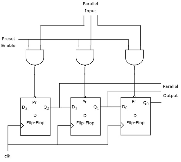
The clock input is a gate-OR structure which allows one input to be used as an active LOW clock enable input ( CE) input. This feature allows parallel-to-serial converter expansion by tying the output Q7 to the input DS of the succeeding stage. It shifts one place to the right (Q0→Q1→Q2, etc.) with each positive-going clock transition. When input PL is HIGH, data enters the register serially at the input DS. When the parallel-load input ( PL) is LOW, parallel data from the inputs D0 to D7 are loaded into the register asynchronously. The 74LV165 is an 8-bit parallel-load or serial-in shift register with complementary serial outputs (Q7 and Q7) available from the last stage. Parallel Input Serial Output Shift Register Verilog CodesĨ-bit parallel-in/serial-out shift register.A shift register basically consists of several single bit “D-Type Data Latches”, one for each data bit, either a logic “0” or a “1”, connected together in a serial type daisy-chain arrangement so that the output from one. This sequential device loads the data present on its inputs and then moves or “shifts” it to its output once every clock cycle, hence the name Shift Register. File: Serial IN Parallel OUT Shift Register using Behavior Modeling Style.v.

Module verilogshiftregistertestPISO( din, clk, load, dout ) output reg dout i.
8 BIT PARALLEL TO SERIAL CONVERTER CIRCUIT DIAGRAM SERIES
I wanted to design a 16 bit parallel in series out shift register. I am learning and practicing Verilog HDL. 22 min - Uploaded by Learn ItParallel input serial output register in vhdl.

8 BIT PARALLEL TO SERIAL CONVERTER CIRCUIT DIAGRAM CODE
Verilog code for an 8-bit shift-left register with a negative-edge clock. Any Veriloga code of a 10-bit parallel in serial out (PISO) shift register.
8 BIT PARALLEL TO SERIAL CONVERTER CIRCUIT DIAGRAM FULL
This delay adds up as the number of full adders/full subtractors increases.Code for an 8-bit shift-left register with a. However, the carry/borrow ports don’t get their inputs till the earlier adder or subtractor are done finishing their operation. What are the disadvantages of a parallel adder and a parallel subtractor?Įach adder or subtractor receives inputs to their A and B ports instantaneously.


 0 kommentar(er)
